We’re now going to discover probably the best part of the series: how to handle lightning! In the previous, we’ve fixed a random color per face to be able to see the mesh. We’re now going to change that to compute the angle between a light and each face to have a better illumination. The first algorithm reviewed is named the Flat Shading. It’s using per face normals. We will still see the polygons using this approach. But thanks to Gouraud Shading, we will go one step further. This one uses per vertex normals. It will then interpolate the color per pixel using 3 normals.
At the end of this tutorial, you should have this very cool rendering:
This tutorial is part of the following series:
1 – Writing the core logic for camera, mesh & device object
2 – Drawing lines and triangles to obtain a wireframe rendering
3 – Loading meshes exported from Blender in a JSON format
4 – Filling the triangle with rasterization and using a Z-Buffer
4b – Bonus: using tips & parallelism to boost the performance
5 – Handling light with Flat Shading & Gouraud Shading (this article)
6 – Applying textures, back-face culling and WebGL
Flat Shading
Concept
To be able to apply the flat shading algorithm, we first need to compute the normal vector of the face. Once we’ve got it, we need to know the angle between this normal vector and the light vector. To be more precise, we’re going to use a dot product that will give us the cosine of the angle between those 2 vectors. As this value could be -1 and 1, we will cut it between 0 and 1. This final value will be used to apply the quantity of light to apply to our face based on its current color. In conclusion, the final color of our face will be = color * Math.Max(0, cos(angle)).
Let’s start by the normal vector. The wikipedia definition Normal (geometry) says that : “For a convex polygon (such as a triangle), a surface normal can be calculated as the vector cross product of two (non-parallel) edges of the polygon”.
To illustrate that, you can see an interesting figure from the Blender documentation: Blender 3D: Noob to Pro – Normal_coordinates

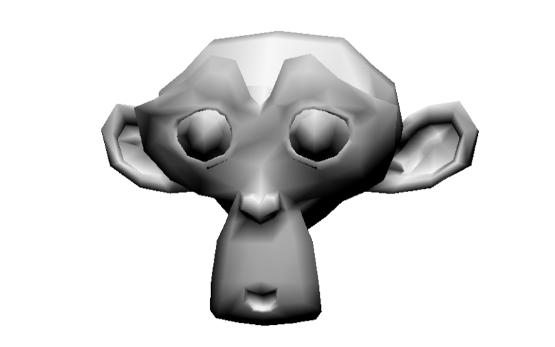
The blue arrows are the normals to the faces. The green and red arrows could be any edge vector of the face. If you want to even better understand where these normal vectors will be, let’s take our Suzanne Blender model as a second illustration.
Open Blender, load the Suzanne mesh, switch into “Edit Mode”:
![]()
Open the properties of the mesh by clicking on it and pressing “N”. Under “Mesh Display”, you’ll find 2 buttons for the normals. Click on the one that says “Display face normals as lines” :

You will obtain something like this:

We need to define a light after that. Our light for these tutorials will be the simplest one: a point light. The point light is then simply a 3D point (a Vector3). The quantity of light that our face will receive will be the same whatever the distance from the light will be. We will then simply vary the intensity based on the angle between the normal vector and the vector made of this point light and the center of our face.
So the light direction will be : lightPosition – centerFacePosition –> this will give us the light direction vector. To compute the angle between this light vector and the normal vector, we will use a dot product : http://en.wikipedia.org/wiki/Dot_product

Figure extracted from: Per-Pixel Lighting (article by John Chapman)
The code
Normally, we would need to first compute the normal vector. Fortunately, Blender is computing those normals for us. Even better, it exports the per vertex normals we will use in the second part. So to compute our normal vector, we just need to take the 3 vertices normals, add them to each other and divide them by 3.
We need to do several refactoring tasks to our code to be able to handle the concepts described before. Up to now, we were only using an array of Vector3 for the vertices. This is not enough anymore. We need more data embedded: the normal associated to the vertex (for the Gouraud Shading) and the 3D projected coordinates. Indeed, the projection is currently done in 2D only. We need to keep 3D coordinates projected into the 3D world to be able to compute the various vectors.
We will then create a structure containing 3 Vector3: the current coordinates we’ve been using so far, the normal to the vertex and the world coordinates.
The ProcessScanLine method will also have to interpolate more data (such as the per vertex normals in the Gouraud Shading). So we’re creating a ScanLineData structure for that.
public class Mesh
{
    public string Name { get; set; }
    public Vertex[] Vertices { get; private set; }
    public Face[] Faces { get; set; }
    public Vector3 Position { get; set; }
    public Vector3 Rotation { get; set; }

    public Mesh(string name, int verticesCount, int facesCount)
    {
        Vertices = new Vertex[verticesCount];
        Faces = new Face[facesCount];
        Name = name;
    }
}

public struct Vertex
{
    public Vector3 Normal;
    public Vector3 Coordinates;
    public Vector3 WorldCoordinates;
}
public struct ScanLineData
{
    public int currentY;
    public float ndotla;
    public float ndotlb;
    public float ndotlc;
    public float ndotld;
}
export interface Vertex {
    Normal: BABYLON.Vector3;
    Coordinates: BABYLON.Vector3;
    WorldCoordinates: BABYLON.Vector3;
}

export class Mesh {
    Position: BABYLON.Vector3;
    Rotation: BABYLON.Vector3;
    Vertices: Vertex[];
    Faces: Face[];

    constructor(public name: string, verticesCount: number, facesCount: number) {
        this.Vertices = new Array(verticesCount);
        this.Faces = new Array(facesCount);
        this.Rotation = new BABYLON.Vector3(0, 0, 0);
        this.Position = new BABYLON.Vector3(0, 0, 0);
    }
}

export interface ScanLineData {
    currentY?: number;
    ndotla?: number;
    ndotlb?: number;
    ndotlc?: number;
    ndotld?: number;
}
This generates various slight modifications to the code. First one is the way to load the JSON file exported by Blender. We now need to load the per vertex normals and build Vertex objects instead of Vector3 objects in the Vertices array:
// Filling the Vertices array of our mesh first
for (var index = 0; index < verticesCount; index++)
{
    var x = (float)verticesArray[index * verticesStep].Value;
    var y = (float)verticesArray[index * verticesStep + 1].Value;
    var z = (float)verticesArray[index * verticesStep + 2].Value;
    // Loading the vertex normal exported by Blender
    var nx = (float)verticesArray[index * verticesStep + 3].Value;
    var ny = (float)verticesArray[index * verticesStep + 4].Value;
    var nz = (float)verticesArray[index * verticesStep + 5].Value;
    mesh.Vertices[index] = new Vertex{ Coordinates= new Vector3(x, y, z), Normal= new Vector3(nx, ny, nz) };
}
// Filling the Vertices array of our mesh first
for (var index = 0; index < verticesCount; index++) {
    var x = verticesArray[index * verticesStep];
    var y = verticesArray[index * verticesStep + 1];
    var z = verticesArray[index * verticesStep + 2];
    // Loading the vertex normal exported by Blender
    var nx = verticesArray[index * verticesStep + 3];
    var ny = verticesArray[index * verticesStep + 4];
    var nz = verticesArray[index * verticesStep + 5];
    mesh.Vertices[index] = {
        Coordinates: new BABYLON.Vector3(x, y, z),
        Normal: new BABYLON.Vector3(nx, ny, nz),
        WorldCoordinates: null
    };
}
Here are all the methods/functions that has been updated:
– Project() is now working on the Vertex structure and is projecting the vertices coordinates in 3D (using the World Matrix) as well as projecting the per vertex normal.
– DrawTriangle() is now getting some Vertex structures as input, compute the NDotL with the ComputeNDotL method and calls ProcessScanLine with those data
– ComputeNDotL() is computing the cosine of the angle between the normal and the light direction
– ProcessScanLine() is now varying the color using the NDotL value sent by DrawTriangle. We currently only have 1 color per triangle as we’re using Flat Shading.
If you’ve been able to digest the previous tutorials and the concept explained at the beginning of this article, simply read the following code and you should now understand the modifications:
// Project takes some 3D coordinates and transform them
// in 2D coordinates using the transformation matrix
// It also transform the same coordinates and the norma to the vertex
// in the 3D world
public Vertex Project(Vertex vertex, Matrix transMat, Matrix world)
{
    // transforming the coordinates into 2D space
    var point2d = Vector3.TransformCoordinate(vertex.Coordinates, transMat);
    // transforming the coordinates & the normal to the vertex in the 3D world
    var point3dWorld = Vector3.TransformCoordinate(vertex.Coordinates, world);
    var normal3dWorld = Vector3.TransformCoordinate(vertex.Normal, world);

    // The transformed coordinates will be based on coordinate system
    // starting on the center of the screen. But drawing on screen normally starts
    // from top left. We then need to transform them again to have x:0, y:0 on top left.
    var x = point2d.X * renderWidth + renderWidth / 2.0f;
    var y = -point2d.Y * renderHeight + renderHeight / 2.0f;

    return new Vertex
    {
        Coordinates = new Vector3(x, y, point2d.Z),
        Normal = normal3dWorld,
        WorldCoordinates = point3dWorld
    };
}

// drawing line between 2 points from left to right
// papb -> pcpd
// pa, pb, pc, pd must then be sorted before
void ProcessScanLine(ScanLineData data, Vertex va, Vertex vb, Vertex vc, Vertex vd, Color4 color)
{
    Vector3 pa = va.Coordinates;
    Vector3 pb = vb.Coordinates;
    Vector3 pc = vc.Coordinates;
    Vector3 pd = vd.Coordinates;

    // Thanks to current Y, we can compute the gradient to compute others values like
    // the starting X (sx) and ending X (ex) to draw between
    // if pa.Y == pb.Y or pc.Y == pd.Y, gradient is forced to 1
    var gradient1 = pa.Y != pb.Y ? (data.currentY - pa.Y) / (pb.Y - pa.Y) : 1;
    var gradient2 = pc.Y != pd.Y ? (data.currentY - pc.Y) / (pd.Y - pc.Y) : 1;

    int sx = (int)Interpolate(pa.X, pb.X, gradient1);
    int ex = (int)Interpolate(pc.X, pd.X, gradient2);

    // starting Z & ending Z
    float z1 = Interpolate(pa.Z, pb.Z, gradient1);
    float z2 = Interpolate(pc.Z, pd.Z, gradient2);

    // drawing a line from left (sx) to right (ex)
    for (var x = sx; x < ex; x++)
    {
        float gradient = (x - sx) / (float)(ex - sx);

        var z = Interpolate(z1, z2, gradient);
        var ndotl = data.ndotla;
        // changing the color value using the cosine of the angle
        // between the light vector and the normal vector
        DrawPoint(new Vector3(x, data.currentY, z), color * ndotl);
    }
}

// Compute the cosine of the angle between the light vector and the normal vector
// Returns a value between 0 and 1
float ComputeNDotL(Vector3 vertex, Vector3 normal, Vector3 lightPosition)
{
    var lightDirection = lightPosition - vertex;

    normal.Normalize();
    lightDirection.Normalize();

    return Math.Max(0, Vector3.Dot(normal, lightDirection));
}

public void DrawTriangle(Vertex v1, Vertex v2, Vertex v3, Color4 color)
{
    // Sorting the points in order to always have this order on screen p1, p2 & p3
    // with p1 always up (thus having the Y the lowest possible to be near the top screen)
    // then p2 between p1 & p3
    if (v1.Coordinates.Y > v2.Coordinates.Y)
    {
        var temp = v2;
        v2 = v1;
        v1 = temp;
    }

    if (v2.Coordinates.Y > v3.Coordinates.Y)
    {
        var temp = v2;
        v2 = v3;
        v3 = temp;
    }

    if (v1.Coordinates.Y > v2.Coordinates.Y)
    {
        var temp = v2;
        v2 = v1;
        v1 = temp;
    }

    Vector3 p1 = v1.Coordinates;
    Vector3 p2 = v2.Coordinates;
    Vector3 p3 = v3.Coordinates;

    // normal face's vector is the average normal between each vertex's normal
    // computing also the center point of the face
    Vector3 vnFace = (v1.Normal + v2.Normal + v3.Normal) / 3;
    Vector3 centerPoint = (v1.WorldCoordinates + v2.WorldCoordinates + v3.WorldCoordinates) / 3;
    // Light position
    Vector3 lightPos = new Vector3(0, 10, 10);
    // computing the cos of the angle between the light vector and the normal vector
    // it will return a value between 0 and 1 that will be used as the intensity of the color
    float ndotl = ComputeNDotL(centerPoint, vnFace, lightPos);

    var data = new ScanLineData { ndotla = ndotl };

    // computing lines' directions
    float dP1P2, dP1P3;

    // http://en.wikipedia.org/wiki/Slope
    // Computing slopes
    if (p2.Y - p1.Y > 0)
        dP1P2 = (p2.X - p1.X) / (p2.Y - p1.Y);
    else
        dP1P2 = 0;

    if (p3.Y - p1.Y > 0)
        dP1P3 = (p3.X - p1.X) / (p3.Y - p1.Y);
    else
        dP1P3 = 0;

    // First case where triangles are like that:
    // P1
    // -
    // --
    // - -
    // -  -
    // -   - P2
    // -  -
    // - -
    // -
    // P3
    if (dP1P2 > dP1P3)
    {
        for (var y = (int)p1.Y; y <= (int)p3.Y; y++)
        {
            data.currentY = y;

            if (y < p2.Y)
            {
                ProcessScanLine(data, v1, v3, v1, v2, color);
            }
            else
            {
                ProcessScanLine(data, v1, v3, v2, v3, color);
            }
        }
    }
    // First case where triangles are like that:
    //       P1
    //        -
    //       --
    //      - -
    //     -  -
    // P2 -   -
    //     -  -
    //      - -
    //        -
    //       P3
    else
    {
        for (var y = (int)p1.Y; y <= (int)p3.Y; y++)
        {
            data.currentY = y;

            if (y < p2.Y)
            {
                ProcessScanLine(data, v1, v2, v1, v3, color);
            }
            else
            {
                ProcessScanLine(data, v2, v3, v1, v3, color);
            }
        }
    }
}
// Project takes some 3D coordinates and transform them
// in 2D coordinates using the transformation matrix
// It also transform the same coordinates and the normal to the vertex
// in the 3D world
public project(vertex: Vertex, transMat: BABYLON.Matrix, world: BABYLON.Matrix): Vertex {
    // transforming the coordinates into 2D space
    var point2d = BABYLON.Vector3.TransformCoordinates(vertex.Coordinates, transMat);
    // transforming the coordinates & the normal to the vertex in the 3D world
    var point3DWorld = BABYLON.Vector3.TransformCoordinates(vertex.Coordinates, world);
    var normal3DWorld = BABYLON.Vector3.TransformCoordinates(vertex.Normal, world);

    // The transformed coordinates will be based on coordinate system
    // starting on the center of the screen. But drawing on screen normally starts
    // from top left. We then need to transform them again to have x:0, y:0 on top left.
    var x = point2d.x * this.workingWidth + this.workingWidth / 2.0;
    var y = -point2d.y * this.workingHeight + this.workingHeight / 2.0;

    return ({
        Coordinates: new BABYLON.Vector3(x, y, point2d.z),
        Normal: normal3DWorld,
        WorldCoordinates: point3DWorld
    });
}

// drawing line between 2 points from left to right
// papb -> pcpd
// pa, pb, pc, pd must then be sorted before
public processScanLine(data: ScanLineData, va: Vertex, vb: Vertex,
                                           vc: Vertex, vd: Vertex, color: BABYLON.Color4): void {
    var pa = va.Coordinates;
    var pb = vb.Coordinates;
    var pc = vc.Coordinates;
    var pd = vd.Coordinates;

    // Thanks to current Y, we can compute the gradient to compute others values like
    // the starting X (sx) and ending X (ex) to draw between
    // if pa.Y == pb.Y or pc.Y == pd.Y, gradient is forced to 1
    var gradient1 = pa.y != pb.y ? (data.currentY - pa.y) / (pb.y - pa.y) : 1;
    var gradient2 = pc.y != pd.y ? (data.currentY - pc.y) / (pd.y - pc.y) : 1;

    var sx = this.interpolate(pa.x, pb.x, gradient1) >> 0;
    var ex = this.interpolate(pc.x, pd.x, gradient2) >> 0;

    // starting Z & ending Z
    var z1: number = this.interpolate(pa.z, pb.z, gradient1);
    var z2: number = this.interpolate(pc.z, pd.z, gradient2);

    // drawing a line from left (sx) to right (ex)
    for (var x = sx; x < ex; x++) {
        var gradient: number = (x - sx) / (ex - sx);

        var z = this.interpolate(z1, z2, gradient);
        var ndotl = data.ndotla;
        // changing the color value using the cosine of the angle
        // between the light vector and the normal vector
        this.drawPoint(new BABYLON.Vector3(x, data.currentY, z),
                       new BABYLON.Color4(color.r * ndotl, color.g * ndotl, color.b * ndotl, 1));
    }
}

// Compute the cosine of the angle between the light vector and the normal vector
// Returns a value between 0 and 1
public computeNDotL(vertex: BABYLON.Vector3, normal: BABYLON.Vector3,
                    lightPosition: BABYLON.Vector3): number {
    var lightDirection = lightPosition.subtract(vertex);

    normal.normalize();
    lightDirection.normalize();

    return Math.max(0, BABYLON.Vector3.Dot(normal, lightDirection));
}

public drawTriangle(v1: Vertex, v2: Vertex, v3: Vertex, color: BABYLON.Color4): void {
    // Sorting the points in order to always have this order on screen p1, p2 & p3
    // with p1 always up (thus having the Y the lowest possible to be near the top screen)
    // then p2 between p1 & p3
    if (v1.Coordinates.y > v2.Coordinates.y) {
        var temp = v2;
        v2 = v1;
        v1 = temp;
    }

    if (v2.Coordinates.y > v3.Coordinates.y) {
        var temp = v2;
        v2 = v3;
        v3 = temp;
    }

    if (v1.Coordinates.y > v2.Coordinates.y) {
        var temp = v2;
        v2 = v1;
        v1 = temp;
    }

    var p1 = v1.Coordinates;
    var p2 = v2.Coordinates;
    var p3 = v3.Coordinates;

    // normal face's vector is the average normal between each vertex's normal
    // computing also the center point of the face
    var vnFace = (v1.Normal.add(v2.Normal.add(v3.Normal))).scale(1 / 3);
    var centerPoint = (v1.WorldCoordinates.add(v2.WorldCoordinates.add(v3.WorldCoordinates))).scale(1 / 3);
    // Light position
    var lightPos = new BABYLON.Vector3(0, 10, 10);
        // computing the cos of the angle between the light vector and the normal vector
    // it will return a value between 0 and 1 that will be used as the intensity of the color
    var ndotl = this.computeNDotL(centerPoint, vnFace, lightPos);

    var data: ScanLineData = { ndotla: ndotl };

    // computing lines' directions
    var dP1P2: number; var dP1P3: number;

    // http://en.wikipedia.org/wiki/Slope
    // Computing slopes
    if (p2.y - p1.y > 0)
        dP1P2 = (p2.x - p1.x) / (p2.y - p1.y);
    else
        dP1P2 = 0;

    if (p3.y - p1.y > 0)
        dP1P3 = (p3.x - p1.x) / (p3.y - p1.y);
    else
        dP1P3 = 0;

    // First case where triangles are like that:
    // P1
    // -
    // --
    // - -
    // -  -
    // -   - P2
    // -  -
    // - -
    // -
    // P3
    if (dP1P2 > dP1P3) {
        for (var y = p1.y >> 0; y <= p3.y >> 0; y++)
        {
            data.currentY = y;

            if (y < p2.y) {
                this.processScanLine(data, v1, v3, v1, v2, color);
            }
            else {
                this.processScanLine(data, v1, v3, v2, v3, color);
            }
        }
    }
    // First case where triangles are like that:
    //       P1
    //        -
    //       --
    //      - -
    //     -  -
    // P2 -   -
    //     -  -
    //      - -
    //        -
    //       P3
    else {
        for (var y = p1.y >> 0; y <= p3.y >> 0; y++)
        {
            data.currentY = y;

            if (y < p2.y) {
                this.processScanLine(data, v1, v2, v1, v3, color);
            }
            else {
                this.processScanLine(data, v2, v3, v1, v3, color);
            }
        }
    }
}
// Project takes some 3D coordinates and transform them
// in 2D coordinates using the transformation matrix
// It also transform the same coordinates and the normal to the vertex
// in the 3D world
Device.prototype.project = function (vertex, transMat, world) {
    // transforming the coordinates into 2D space
    var point2d = BABYLON.Vector3.TransformCoordinates(vertex.Coordinates, transMat);
    // transforming the coordinates & the normal to the vertex in the 3D world
    var point3DWorld = BABYLON.Vector3.TransformCoordinates(vertex.Coordinates, world);
    var normal3DWorld = BABYLON.Vector3.TransformCoordinates(vertex.Normal, world);

    // The transformed coordinates will be based on coordinate system
    // starting on the center of the screen. But drawing on screen normally starts
    // from top left. We then need to transform them again to have x:0, y:0 on top left.
    var x = point2d.x * this.workingWidth + this.workingWidth / 2.0;
    var y = -point2d.y * this.workingHeight + this.workingHeight / 2.0;

    return ({
        Coordinates: new BABYLON.Vector3(x, y, point2d.z),
        Normal: normal3DWorld,
        WorldCoordinates: point3DWorld
    });
};

// drawing line between 2 points from left to right
// papb -> pcpd
// pa, pb, pc, pd must then be sorted before
Device.prototype.processScanLine = function (data, va, vb, vc, vd, color) {
    var pa = va.Coordinates;
    var pb = vb.Coordinates;
    var pc = vc.Coordinates;
    var pd = vd.Coordinates;

    // Thanks to current Y, we can compute the gradient to compute others values like
    // the starting X (sx) and ending X (ex) to draw between
    // if pa.Y == pb.Y or pc.Y == pd.Y, gradient is forced to 1
    var gradient1 = pa.y != pb.y ? (data.currentY - pa.y) / (pb.y - pa.y) : 1;
    var gradient2 = pc.y != pd.y ? (data.currentY - pc.y) / (pd.y - pc.y) : 1;

    var sx = this.interpolate(pa.x, pb.x, gradient1) >> 0;
    var ex = this.interpolate(pc.x, pd.x, gradient2) >> 0;

    // starting Z & ending Z
    var z1 = this.interpolate(pa.z, pb.z, gradient1);
    var z2 = this.interpolate(pc.z, pd.z, gradient2);

    // drawing a line from left (sx) to right (
    for (var x = sx; x < ex; x++) {
        var gradient = (x - sx) / (ex - sx);

        var z = this.interpolate(z1, z2, gradient);
        var ndotl = data.ndotla;
        // changing the color value using the cosine of the angle
        // between the light vector and the normal vector
        this.drawPoint(new BABYLON.Vector3(x, data.currentY, z),
                       new BABYLON.Color4(color.r * ndotl, color.g * ndotl, color.b * ndotl, 1));
    }
};

// Compute the cosine of the angle between the light vector and the normal vector
// Returns a value between 0 and 1
Device.prototype.computeNDotL = function (vertex, normal, lightPosition) {
    var lightDirection = lightPosition.subtract(vertex);

    normal.normalize();
    lightDirection.normalize();

    return Math.max(0, BABYLON.Vector3.Dot(normal, lightDirection));
};

Device.prototype.drawTriangle = function (v1, v2, v3, color) {
    // Sorting the points in order to always have this order on screen p1, p2 & p3
    // with p1 always up (thus having the Y the lowest possible to be near the top screen)
    // then p2 between p1 & p3
    if (v1.Coordinates.y > v2.Coordinates.y) {
        var temp = v2;
        v2 = v1;
        v1 = temp;
    }

    if (v2.Coordinates.y > v3.Coordinates.y) {
        var temp = v2;
        v2 = v3;
        v3 = temp;
    }

    if (v1.Coordinates.y > v2.Coordinates.y) {
        var temp = v2;
        v2 = v1;
        v1 = temp;
    }

    var p1 = v1.Coordinates;
    var p2 = v2.Coordinates;
    var p3 = v3.Coordinates;

    // normal face's vector is the average normal between each vertex's normal
    // computing also the center point of the face
    var vnFace = (v1.Normal.add(v2.Normal.add(v3.Normal))).scale(1 / 3);
    var centerPoint = (v1.WorldCoordinates.add(v2.WorldCoordinates.add(v3.WorldCoordinates))).scale(1 / 3);
    // Light position
    var lightPos = new BABYLON.Vector3(0, 10, 10);
    // computing the cos of the angle between the light vector and the normal vector
    // it will return a value between 0 and 1 that will be used as the intensity of the color
    var ndotl = this.computeNDotL(centerPoint, vnFace, lightPos);

    var data = { ndotla: ndotl };

    // computing lines' directions
    var dP1P2;
    var dP1P3;

    // http://en.wikipedia.org/wiki/Slope
    // Computing slopes
    if (p2.y - p1.y > 0)
        dP1P2 = (p2.x - p1.x) / (p2.y - p1.y); else
        dP1P2 = 0;

    if (p3.y - p1.y > 0)
        dP1P3 = (p3.x - p1.x) / (p3.y - p1.y); else
        dP1P3 = 0;

    // First case where triangles are like that:
    // P1
    // -
    // --
    // - -
    // -  -
    // -   - P2
    // -  -
    // - -
    // -
    // P3
    if (dP1P2 > dP1P3) {
        for (var y = p1.y >> 0; y <= p3.y >> 0; y++) {
            data.currentY = y;

            if (y < p2.y) {
                this.processScanLine(data, v1, v3, v1, v2, color);
            } else {
                this.processScanLine(data, v1, v3, v2, v3, color);
            }
        }
    }
    // First case where triangles are like that:
    //       P1
    //        -
    //       --
    //      - -
    //     -  -
    // P2 -   -
    //     -  -
    //      - -
    //        -
    //       P3
    else {
        for (var y = p1.y >> 0; y <= p3.y >> 0; y++) {
            data.currentY = y;

            if (y < p2.y) {
                this.processScanLine(data, v1, v2, v1, v3, color);
            } else {
                this.processScanLine(data, v2, v3, v1, v3, color);
            }
        }
    }
};
To view the result in your browser, click on the screenshot below:

3D Software engine : view the Flat Shading demo in HTML5 in your browser
On my Lenovo X1 Carbon (core i7 Ivy Bridge), I’m running this 640×480 rendering around 35 FPS in Internet Explorer 11 (which seems to be the fastest browser for this demo on my Windows 8.1 machine) and around 4 FPS on IE11 on Surface RT. The C# parallelized version runs the same scene in 640×480 at 60 FPS.
You can download the solution implementing this Flat Shading here:
– C# : SoftEngineCSharpPart5FlatShading.zip
– TypeScript : SoftEngineTSPart5FlatShading.zip
– JavaScript : SoftEngineJSPart5FlatShading.zip or simply right-click –> view source on the first embedded iframe
Gouraud Shading
Concept
If you’ve managed to understand the Flat Shading, you’ll see that the Gouraud Shading is not complex at all. This time, rather than using 1 unique normal per face, and thus a unique color per face, we’re going to use 3 normals: 1 per vertex of our triangles. We will then have 3 level of colors defined and we will interpolate the color of each pixel between each vertex using the same algorithm used in previous tutorials. Using this interpolation, we will then have a continuous lightning on our triangles.

Extracted from: Tutorial 5. Terrain – Light & Vertex Normal Vector
You can see in this figure the differences between flat shading and gouraud shading. The flat uses a centered unique normal and the gouraud uses 3 normals. You see also on a 3D mesh (the pyramid) that the normal is per vertex per face. I mean that the same vertex will have different normals based on the face we’re currently drawing.
Let’s go back to the draw triangle logic. Another good way to understand what we’ll do with the shading is illustrated here:
Extracted from: TUTORIALS – CREATING NORMAL MAPS by Ben Cloward
In this figure, imagine that the upper vertex normal has an angle > 90 degrees with the light direction, it’s color should then be black (minimum level of light = 0). Imagine now that the 2 other vertex normal has an angle of 0 degree with the light direction, this means that they should receive the maximum level of light (1).
To fill our triangle, we’re then going to interpolate to color level between each vertex to have a nice gradient.
The code
As the code is pretty straightforward, simply read it and you’ll see where I’m implementing the interpolation of the color.
// drawing line between 2 points from left to right
// papb -> pcpd
// pa, pb, pc, pd must then be sorted before
void ProcessScanLine(ScanLineData data, Vertex va, Vertex vb, Vertex vc, Vertex vd, Color4 color)
{
    Vector3 pa = va.Coordinates;
    Vector3 pb = vb.Coordinates;
    Vector3 pc = vc.Coordinates;
    Vector3 pd = vd.Coordinates;

    // Thanks to current Y, we can compute the gradient to compute others values like
    // the starting X (sx) and ending X (ex) to draw between
    // if pa.Y == pb.Y or pc.Y == pd.Y, gradient is forced to 1
    var gradient1 = pa.Y != pb.Y ? (data.currentY - pa.Y) / (pb.Y - pa.Y) : 1;
    var gradient2 = pc.Y != pd.Y ? (data.currentY - pc.Y) / (pd.Y - pc.Y) : 1;

    int sx = (int)Interpolate(pa.X, pb.X, gradient1);
    int ex = (int)Interpolate(pc.X, pd.X, gradient2);

    // starting Z & ending Z
    float z1 = Interpolate(pa.Z, pb.Z, gradient1);
    float z2 = Interpolate(pc.Z, pd.Z, gradient2);

    var snl = Interpolate(data.ndotla, data.ndotlb, gradient1);
    var enl = Interpolate(data.ndotlc, data.ndotld, gradient2);

    // drawing a line from left (sx) to right (ex)
    for (var x = sx; x < ex; x++)
    {
        float gradient = (x - sx) / (float)(ex - sx);

        var z = Interpolate(z1, z2, gradient);
        var ndotl = Interpolate(snl, enl, gradient);
        // changing the color value using the cosine of the angle
        // between the light vector and the normal vector
        DrawPoint(new Vector3(x, data.currentY, z), color * ndotl);
    }
}

public void DrawTriangle(Vertex v1, Vertex v2, Vertex v3, Color4 color)
{
    // Sorting the points in order to always have this order on screen p1, p2 & p3
    // with p1 always up (thus having the Y the lowest possible to be near the top screen)
    // then p2 between p1 & p3
    if (v1.Coordinates.Y > v2.Coordinates.Y)
    {
        var temp = v2;
        v2 = v1;
        v1 = temp;
    }

    if (v2.Coordinates.Y > v3.Coordinates.Y)
    {
        var temp = v2;
        v2 = v3;
        v3 = temp;
    }

    if (v1.Coordinates.Y > v2.Coordinates.Y)
    {
        var temp = v2;
        v2 = v1;
        v1 = temp;
    }

    Vector3 p1 = v1.Coordinates;
    Vector3 p2 = v2.Coordinates;
    Vector3 p3 = v3.Coordinates;

    // Light position
    Vector3 lightPos = new Vector3(0, 10, 10);
    // computing the cos of the angle between the light vector and the normal vector
    // it will return a value between 0 and 1 that will be used as the intensity of the color
    float nl1 = ComputeNDotL(v1.WorldCoordinates, v1.Normal, lightPos);
    float nl2 = ComputeNDotL(v2.WorldCoordinates, v2.Normal, lightPos);
    float nl3 = ComputeNDotL(v3.WorldCoordinates, v3.Normal, lightPos);

    var data = new ScanLineData { };

    // computing lines' directions
    float dP1P2, dP1P3;

    // http://en.wikipedia.org/wiki/Slope
    // Computing slopes
    if (p2.Y - p1.Y > 0)
        dP1P2 = (p2.X - p1.X) / (p2.Y - p1.Y);
    else
        dP1P2 = 0;

    if (p3.Y - p1.Y > 0)
        dP1P3 = (p3.X - p1.X) / (p3.Y - p1.Y);
    else
        dP1P3 = 0;

    if (dP1P2 > dP1P3)
    {
        for (var y = (int)p1.Y; y <= (int)p3.Y; y++)
        {
            data.currentY = y;

            if (y < p2.Y)
            {
                data.ndotla = nl1;
                data.ndotlb = nl3;
                data.ndotlc = nl1;
                data.ndotld = nl2;
                ProcessScanLine(data, v1, v3, v1, v2, color);
            }
            else
            {
                data.ndotla = nl1;
                data.ndotlb = nl3;
                data.ndotlc = nl2;
                data.ndotld = nl3;
                ProcessScanLine(data, v1, v3, v2, v3, color);
            }
        }
    }
    else
    {
        for (var y = (int)p1.Y; y <= (int)p3.Y; y++)
        {
            data.currentY = y;

            if (y < p2.Y)
            {
                data.ndotla = nl1;
                data.ndotlb = nl2;
                data.ndotlc = nl1;
                data.ndotld = nl3;
                ProcessScanLine(data, v1, v2, v1, v3, color);
            }
            else
            {
                data.ndotla = nl2;
                data.ndotlb = nl3;
                data.ndotlc = nl1;
                data.ndotld = nl3;
                ProcessScanLine(data, v2, v3, v1, v3, color);
            }
        }
    }
}
// drawing line between 2 points from left to right
// papb -> pcpd
// pa, pb, pc, pd must then be sorted before
public processScanLine(data: ScanLineData, va: Vertex, vb: Vertex,
                                           vc: Vertex, vd: Vertex, color: BABYLON.Color4): void {
    var pa = va.Coordinates;
    var pb = vb.Coordinates;
    var pc = vc.Coordinates;
    var pd = vd.Coordinates;

    // Thanks to current Y, we can compute the gradient to compute others values like
    // the starting X (sx) and ending X (ex) to draw between
    // if pa.Y == pb.Y or pc.Y == pd.Y, gradient is forced to 1
    var gradient1 = pa.y != pb.y ? (data.currentY - pa.y) / (pb.y - pa.y) : 1;
    var gradient2 = pc.y != pd.y ? (data.currentY - pc.y) / (pd.y - pc.y) : 1;

    var sx = this.interpolate(pa.x, pb.x, gradient1) >> 0;
    var ex = this.interpolate(pc.x, pd.x, gradient2) >> 0;

    // starting Z & ending Z
    var z1: number = this.interpolate(pa.z, pb.z, gradient1);
    var z2: number = this.interpolate(pc.z, pd.z, gradient2);

    var snl = this.interpolate(data.ndotla, data.ndotlb, gradient1);
    var enl = this.interpolate(data.ndotlc, data.ndotld, gradient2);

    // drawing a line from left (sx) to right (ex)
    for (var x = sx; x < ex; x++) {
        var gradient: number = (x - sx) / (ex - sx);

        var z = this.interpolate(z1, z2, gradient);
        var ndotl = this.interpolate(snl, enl, gradient);
        // changing the color value using the cosine of the angle
        // between the light vector and the normal vector
        this.drawPoint(new BABYLON.Vector3(x, data.currentY, z),
                       new BABYLON.Color4(color.r * ndotl, color.g * ndotl, color.b * ndotl, 1));
    }
}

public drawTriangle(v1: Vertex, v2: Vertex, v3: Vertex, color: BABYLON.Color4): void {
    // Sorting the points in order to always have this order on screen p1, p2 & p3
    // with p1 always up (thus having the Y the lowest possible to be near the top screen)
    // then p2 between p1 & p3
    if (v1.Coordinates.y > v2.Coordinates.y) {
        var temp = v2;
        v2 = v1;
        v1 = temp;
    }

    if (v2.Coordinates.y > v3.Coordinates.y) {
        var temp = v2;
        v2 = v3;
        v3 = temp;
    }

    if (v1.Coordinates.y > v2.Coordinates.y) {
        var temp = v2;
        v2 = v1;
        v1 = temp;
    }

    var p1 = v1.Coordinates;
    var p2 = v2.Coordinates;
    var p3 = v3.Coordinates;

    // Light position
    var lightPos = new BABYLON.Vector3(0, 10, 10);
    // computing the cos of the angle between the light vector and the normal vector
    // it will return a value between 0 and 1 that will be used as the intensity of the color
    //var ndotl = this.computeNDotL(centerPoint, vnFace, lightPos);
    var nl1 = this.computeNDotL(v1.WorldCoordinates, v1.Normal, lightPos);
    var nl2 = this.computeNDotL(v2.WorldCoordinates, v2.Normal, lightPos);
    var nl3 = this.computeNDotL(v3.WorldCoordinates, v3.Normal, lightPos);

    var data: ScanLineData = { };

    // computing lines' directions
    var dP1P2: number; var dP1P3: number;

    // http://en.wikipedia.org/wiki/Slope
    // Computing slopes
    if (p2.y - p1.y > 0)
        dP1P2 = (p2.x - p1.x) / (p2.y - p1.y);
    else
        dP1P2 = 0;

    if (p3.y - p1.y > 0)
        dP1P3 = (p3.x - p1.x) / (p3.y - p1.y);
    else
        dP1P3 = 0;

    if (dP1P2 > dP1P3) {
        for (var y = p1.y >> 0; y <= p3.y >> 0; y++)
        {
            data.currentY = y;

            if (y < p2.y) {
                data.ndotla = nl1;
                data.ndotlb = nl3;
                data.ndotlc = nl1;
                data.ndotld = nl2;
                this.processScanLine(data, v1, v3, v1, v2, color);
            }
            else {
                data.ndotla = nl1;
                data.ndotlb = nl3;
                data.ndotlc = nl2;
                data.ndotld = nl3;
                this.processScanLine(data, v1, v3, v2, v3, color);
            }
        }
    }
    else {
        for (var y = p1.y >> 0; y <= p3.y >> 0; y++)
        {
            data.currentY = y;

            if (y < p2.y) {
                data.ndotla = nl1;
                data.ndotlb = nl2;
                data.ndotlc = nl1;
                data.ndotld = nl3;
                this.processScanLine(data, v1, v2, v1, v3, color);
            }
            else {
                data.ndotla = nl2;
                data.ndotlb = nl3;
                data.ndotlc = nl1;
                data.ndotld = nl3;
                this.processScanLine(data, v2, v3, v1, v3, color);
            }
        }
    }
}
// drawing line between 2 points from left to right
// papb -> pcpd
// pa, pb, pc, pd must then be sorted before
Device.prototype.processScanLine = function (data, va, vb, vc, vd, color) {
    var pa = va.Coordinates;
    var pb = vb.Coordinates;
    var pc = vc.Coordinates;
    var pd = vd.Coordinates;

    // Thanks to current Y, we can compute the gradient to compute others values like
    // the starting X (sx) and ending X (ex) to draw between
    // if pa.Y == pb.Y or pc.Y == pd.Y, gradient is forced to 1
    var gradient1 = pa.y != pb.y ? (data.currentY - pa.y) / (pb.y - pa.y) : 1;
    var gradient2 = pc.y != pd.y ? (data.currentY - pc.y) / (pd.y - pc.y) : 1;

    var sx = this.interpolate(pa.x, pb.x, gradient1) >> 0;
    var ex = this.interpolate(pc.x, pd.x, gradient2) >> 0;

    // starting Z & ending Z
    var z1 = this.interpolate(pa.z, pb.z, gradient1);
    var z2 = this.interpolate(pc.z, pd.z, gradient2);

    var snl = this.interpolate(data.ndotla, data.ndotlb, gradient1);
    var enl = this.interpolate(data.ndotlc, data.ndotld, gradient2);

    // drawing a line from left (sx) to right (ex)
    for (var x = sx; x < ex; x++) {
        var gradient = (x - sx) / (ex - sx);

        var z = this.interpolate(z1, z2, gradient);
        var ndotl = this.interpolate(snl, enl, gradient);
        // changing the color value using the cosine of the angle
        // between the light vector and the normal vector
        this.drawPoint(new BABYLON.Vector3(x, data.currentY, z),
                       new BABYLON.Color4(color.r * ndotl, color.g * ndotl, color.b * ndotl, 1));
    }
};

Device.prototype.drawTriangle = function (v1, v2, v3, color) {
    // Sorting the points in order to always have this order on screen p1, p2 & p3
    // with p1 always up (thus having the Y the lowest possible to be near the top screen)
    // then p2 between p1 & p3
    if (v1.Coordinates.y > v2.Coordinates.y) {
        var temp = v2;
        v2 = v1;
        v1 = temp;
    }

    if (v2.Coordinates.y > v3.Coordinates.y) {
        var temp = v2;
        v2 = v3;
        v3 = temp;
    }

    if (v1.Coordinates.y > v2.Coordinates.y) {
        var temp = v2;
        v2 = v1;
        v1 = temp;
    }

    var p1 = v1.Coordinates;
    var p2 = v2.Coordinates;
    var p3 = v3.Coordinates;

    // Light position
    var lightPos = new BABYLON.Vector3(0, 10, 10);
    // computing the cos of the angle between the light vector and the normal vector
    // it will return a value between 0 and 1 that will be used as the intensity of the color
    var nl1 = this.computeNDotL(v1.WorldCoordinates, v1.Normal, lightPos);
    var nl2 = this.computeNDotL(v2.WorldCoordinates, v2.Normal, lightPos);
    var nl3 = this.computeNDotL(v3.WorldCoordinates, v3.Normal, lightPos);

    var data = {};

    // computing lines' directions
    var dP1P2;
    var dP1P3;

    // http://en.wikipedia.org/wiki/Slope
    // Computing slopes
    if (p2.y - p1.y > 0)
        dP1P2 = (p2.x - p1.x) / (p2.y - p1.y); else
        dP1P2 = 0;

    if (p3.y - p1.y > 0)
        dP1P3 = (p3.x - p1.x) / (p3.y - p1.y); else
        dP1P3 = 0;

    if (dP1P2 > dP1P3) {
        for (var y = p1.y >> 0; y <= p3.y >> 0; y++) {
            data.currentY = y;

            if (y < p2.y) {
                data.ndotla = nl1;
                data.ndotlb = nl3;
                data.ndotlc = nl1;
                data.ndotld = nl2;
                this.processScanLine(data, v1, v3, v1, v2, color);
            } else {
                data.ndotla = nl1;
                data.ndotlb = nl3;
                data.ndotlc = nl2;
                data.ndotld = nl3;
                this.processScanLine(data, v1, v3, v2, v3, color);
            }
        }
    }
    else {
        for (var y = p1.y >> 0; y <= p3.y >> 0; y++) {
            data.currentY = y;

            if (y < p2.y) {
                data.ndotla = nl1;
                data.ndotlb = nl2;
                data.ndotlc = nl1;
                data.ndotld = nl3;
                this.processScanLine(data, v1, v2, v1, v3, color);
            } else {
                data.ndotla = nl2;
                data.ndotlb = nl3;
                data.ndotlc = nl1;
                data.ndotld = nl3;
                this.processScanLine(data, v2, v3, v1, v3, color);
            }
        }
    }
};
To view the result in your browser, click on the screenshot below:

3D Software engine : view the Gouraud Shading demo in HTML5 in your browser
You’ll see that the performance/FPS are almost the same that with the Flat Shading algorithm but with a much nicer rendering. There is an even better algorithm named the Phong Shading with uses this time per pixel normals.
Here is another scene to test in your HTML5 browser. It uses a Torus mesh exported from Blender:

3D Software engine : view the Gouraud Shading demo with a Torus
You can download the solution implementing this Gouraud Shading here:
– C# : SoftEngineCSharpPart5GouraudShading.zip
– TypeScript : SoftEngineTSPart5GouraudShading.zip
– JavaScript : SoftEngineJSPart5GouraudShading.zip or simply right-click –> view source on the first embedded iframe
In the next & final tutorial, we’ll see how to apply a texture to our mesh and we will obtain this kind of rendering:

And we will also see the exact same 3D object in a WebGL engine. You’ll then understand why GPU are so important to boost the performance of a real-time 3D renderer!
Awesome and very impressed by your knowledge in the area.
Thanks for a really great in-depth presentation. These are the best that I have seen. I am looking forward to the next lesson!
In javascript, a guide (sentence or something) is missing to add the worldMatrix reference to the project methods' arguments in the render method.
hello,i think that normal vector should be calculated with every rotation why do you get them form blender and do they are static value!!..i wonder also what are world coordination.
world coordinates = global coordinates.
Thanks for the guide! But seems there is a problem. Are you sure in this line:
var normal3DWorld = BABYLON.Vector3.TransformCoordinates(vertex.Normal, world);
?
Why do you transform the normal using world matrix? This seems not right and as consequence of this mistake: if an face has negative z coordinates then lighting make the face always black even if the face is turned to the light.
The right normal matrix to world space should be : transpose(inverse(world_matrix))
This doesn’t seem to be the complete solution as I have completed everything and it just ends up being the flat shading.