In the previous tutorial, learning how to write a 3D soft engine in C#, TS or JS – loading meshes exported from Blender, we’ve loaded a JSON file where our meshes were serialized from Blender. Up to now, our render function was drawing the meshes with only a simple wireframe rendering. We’re now going to see how to fill the triangles using a rasterization algorithm. Then, we’ll see how to handle a Z-Buffer to avoid having faces living in the back being drawn on top on front faces.
This tutorial is part of the following series:
1 – Writing the core logic for camera, mesh & device object
2 – Drawing lines and triangles to obtain a wireframe rendering
3 – Loading meshes exported from Blender in a JSON format
4 – Filling the triangle with rasterization and using a Z-Buffer (this article)
4b – Bonus: using tips & parallelism to boost the performance
5 – Handling light with Flat Shading & Gouraud Shading
6 – Applying textures, back-face culling and WebGL
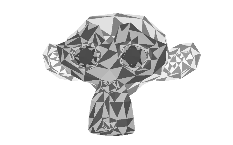
By following this tutorial, you will be able to have such rendering:
Rasterization
There’s a lot of different types of rasterization algorithms. I even know someone in my team who has made his own patented rasterization algorithm for a well known GPU maker. It’s also thanks to him that I now know what Boustrophedon is and it has really changed my life since then. 🙂
To be more serious, we’re going to implement in this tutorial a simple but efficient rasterization algorithm. As we’re running on CPU with our 3D software engine, we must pay a lot of attention to this part. Indeed, it will to cost us a lot of CPU. Today, of course, this heavy part is done directly by GPUs.
Let’s start by an exercise. Take a piece of paper and start drawing all the types of triangles you could think of. The idea is to find a generic way to draw any type of triangles.
If we’re sorting the three vertices of each triangle on the Y coordinates in order to always have P1 followed by P2 followed by P3, we will finally only have 2 possible cases:

You then see that we have 2 cases: P2 is on the right of P1P3 or P2 is on the left of P1P3. In our case, as we want to always draw our lines from left to right from sx to ex, we will have a first conditional IF to handle these 2 cases.
Moreover, we’re going to draw from left to right by moving down from P1.Y to P3.Y following the red line drawn on the left case of the figure. But we will need to change our logic reaching P2.Y as the slope will change in both cases. That’s why, we’ve got 2 steps in the scan line process. Moving down from P1.Y to P2.Y and then from P2.Y to P3.Y, our final destination.
All the logic needed to understand how to build our algorithm is described on Wikipedia: http://en.wikipedia.org/wiki/Slope . This is really some basic math.
To be able to sort the cases between case 1 and case 2, you simply need to compute the inverse slopes in this way:
dP1P2 = P2.X – P1.X / P2.Y – P1.Y and dP1P3 = P3.X – P1.X / P3.Y – P1.Y
If dP1P2 > dP1P3 then we are in the first case with P2 on the right, otherwise if dP1P2 > dP1P2, we are in the second case with P2 on the left.
Now that we have the basic logic of our algorithm, we need to know how to compute X on each line between SX (Start X) and EX (End X) on my figure. So we need to compute SX & EX first. As we know the Y value and the slope P1P3 & P1P2, we can easily find SX & EX we’re interested in.
Let’s take the step 1 of the case 1 as an example. First step is to compute our gradient with the current Y value in our loop. It will tell us at which stage we are in the scan line processing between P1.Y and P2.Y in Step 1.
gradient = currentY – P1.Y / P2.Y – P1.Y
As X and Y are linearly linked, we can interpolate SX based on this gradient using P1.X and P3.X & interpolate EX using P1.X and P2.X.
If you manage to understand this concept of interpolation, you will be able to understand all the remaining tutorials to handle light & texture. You then definitely need to spend time on reading the associated code. You need also to be sure you’d be able to rebuild it from scratch yourself without copy/pasting the code below.
If it’s still not clear enough, here are other interesting articles to read addressing also rasterization:
– 3D Software Rendering Engine – Part I
– Triangle Rasterization
– Software Rasterization Algorithms for filling triangles
Now that we have our algorithm described. Let’s now work on the code. Start by removing the drawLine and drawBline from the device class. Then, replace your existing functions/methods by those one:
// Project takes some 3D coordinates and transform them
// in 2D coordinates using the transformation matrix
public Vector3 Project(Vector3 coord, Matrix transMat)
{
    // transforming the coordinates
    var point = Vector3.TransformCoordinate(coord, transMat);
    // The transformed coordinates will be based on coordinate system
    // starting on the center of the screen. But drawing on screen normally starts
    // from top left. We then need to transform them again to have x:0, y:0 on top left.
    var x = point.X * bmp.PixelWidth + bmp.PixelWidth / 2.0f;
    var y = -point.Y * bmp.PixelHeight + bmp.PixelHeight / 2.0f;
    return (new Vector3(x, y, point.Z));
}

// DrawPoint calls PutPixel but does the clipping operation before
public void DrawPoint(Vector2 point, Color4 color)
{
    // Clipping what's visible on screen
    if (point.X >= 0 && point.Y >= 0 && point.X < bmp.PixelWidth && point.Y < bmp.PixelHeight)
    {
        // Drawing a point
        PutPixel((int)point.X, (int)point.Y, color);
    }
}
// Project takes some 3D coordinates and transform them
// in 2D coordinates using the transformation matrix
public project(coord: BABYLON.Vector3, transMat: BABYLON.Matrix): BABYLON.Vector3 {
    // transforming the coordinates
    var point = BABYLON.Vector3.TransformCoordinates(coord, transMat);
    // The transformed coordinates will be based on coordinate system
    // starting on the center of the screen. But drawing on screen normally starts
    // from top left. We then need to transform them again to have x:0, y:0 on top left.
    var x = point.x * this.workingWidth + this.workingWidth / 2.0;
    var y = -point.y * this.workingHeight + this.workingHeight / 2.0;
    return (new BABYLON.Vector3(x, y, point.z));
}

// drawPoint calls putPixel but does the clipping operation before
public drawPoint(point: BABYLON.Vector2, color: BABYLON.Color4): void {
    // Clipping what's visible on screen
    if (point.x >= 0 && point.y >= 0 && point.x < this.workingWidth && point.y < this.workingHeight) {
        // Drawing a yellow point
        this.putPixel(point.x, point.y, color);
    }
}
// Project takes some 3D coordinates and transform them
// in 2D coordinates using the transformation matrix
Device.prototype.project = function (coord, transMat) {
    var point = BABYLON.Vector3.TransformCoordinates(coord, transMat);
    // The transformed coordinates will be based on coordinate system
    // starting on the center of the screen. But drawing on screen normally starts
    // from top left. We then need to transform them again to have x:0, y:0 on top left.
    var x = point.x * this.workingWidth + this.workingWidth / 2.0 >> 0;
    var y = -point.y * this.workingHeight + this.workingHeight / 2.0 >> 0;
    return (new BABYLON.Vector3(x, y, point.z));
};

// drawPoint calls putPixel but does the clipping operation before
Device.prototype.drawPoint = function (point, color) {
    // Clipping what's visible on screen
    if (point.x >= 0 && point.y >= 0 && point.x < this.workingWidth
                                        && point.y < this.workingHeight) {
        // Drawing a yellow point
        this.putPixel(point.x, point.y, color);
    }
};
We’re just preparing some stuff for the second part of this tutorial. Now, here is the most important part. Here is the logic that going to draw the triangles based on the previous explanations.
// Clamping values to keep them between 0 and 1
float Clamp(float value, float min = 0, float max = 1)
{
    return Math.Max(min, Math.Min(value, max));
}

// Interpolating the value between 2 vertices
// min is the starting point, max the ending point
// and gradient the % between the 2 points
float Interpolate(float min, float max, float gradient)
{
    return min + (max - min) * Clamp(gradient);
}

// drawing line between 2 points from left to right
// papb -> pcpd
// pa, pb, pc, pd must then be sorted before
void ProcessScanLine(int y, Vector3 pa, Vector3 pb, Vector3 pc, Vector3 pd, Color4 color)
{
    // Thanks to current Y, we can compute the gradient to compute others values like
    // the starting X (sx) and ending X (ex) to draw between
    // if pa.Y == pb.Y or pc.Y == pd.Y, gradient is forced to 1
    var gradient1 = pa.Y != pb.Y ? (y - pa.Y) / (pb.Y - pa.Y) : 1;
    var gradient2 = pc.Y != pd.Y ? (y - pc.Y) / (pd.Y - pc.Y) : 1;

    int sx = (int)Interpolate(pa.X, pb.X, gradient1);
    int ex = (int)Interpolate(pc.X, pd.X, gradient2);

    // drawing a line from left (sx) to right (ex)
    for (var x = sx; x < ex; x++)
    {
        DrawPoint(new Vector2(x, y), color);
    }
}

public void DrawTriangle(Vector3 p1, Vector3 p2, Vector3 p3, Color4 color)
{
    // Sorting the points in order to always have this order on screen p1, p2 & p3
    // with p1 always up (thus having the Y the lowest possible to be near the top screen)
    // then p2 between p1 & p3
    if (p1.Y > p2.Y)
    {
        var temp = p2;
        p2 = p1;
        p1 = temp;
    }

    if (p2.Y > p3.Y)
    {
        var temp = p2;
        p2 = p3;
        p3 = temp;
    }

    if (p1.Y > p2.Y)
    {
        var temp = p2;
        p2 = p1;
        p1 = temp;
    }

    // inverse slopes
    float dP1P2, dP1P3;

    // http://en.wikipedia.org/wiki/Slope
    // Computing inverse slopes
    if (p2.Y - p1.Y > 0)
        dP1P2 = (p2.X - p1.X) / (p2.Y - p1.Y);
    else
        dP1P2 = 0;

    if (p3.Y - p1.Y > 0)
        dP1P3 = (p3.X - p1.X) / (p3.Y - p1.Y);
    else
        dP1P3 = 0;

    // First case where triangles are like that:
    // P1
    // -
    // --
    // - -
    // -  -
    // -   - P2
    // -  -
    // - -
    // -
    // P3
    if (dP1P2 > dP1P3)
    {
        for (var y = (int)p1.Y; y <= (int)p3.Y; y++)
        {
            if (y < p2.Y)
            {
                ProcessScanLine(y, p1, p3, p1, p2, color);
            }
            else
            {
                ProcessScanLine(y, p1, p3, p2, p3, color);
            }
        }
    }
    // First case where triangles are like that:
    //       P1
    //        -
    //       --
    //      - -
    //     -  -
    // P2 -   -
    //     -  -
    //      - -
    //        -
    //       P3
    else
    {
        for (var y = (int)p1.Y; y <= (int)p3.Y; y++)
        {
            if (y < p2.Y)
            {
                ProcessScanLine(y, p1, p2, p1, p3, color);
            }
            else
            {
                ProcessScanLine(y, p2, p3, p1, p3, color);
            }
        }
    }
}
// Clamping values to keep them between 0 and 1
public clamp(value: number, min: number = 0, max: number = 1): number {
    return Math.max(min, Math.min(value, max));
}

// Interpolating the value between 2 vertices
// min is the starting point, max the ending point
// and gradient the % between the 2 points
public interpolate(min: number, max: number, gradient: number) {
    return min + (max - min) * this.clamp(gradient);
}

// drawing line between 2 points from left to right
// papb -> pcpd
// pa, pb, pc, pd must then be sorted before
public processScanLine(y: number, pa: BABYLON.Vector3, pb: BABYLON.Vector3,
                       pc: BABYLON.Vector3, pd: BABYLON.Vector3, color: BABYLON.Color4): void {
    // Thanks to current Y, we can compute the gradient to compute others values like
    // the starting X (sx) and ending X (ex) to draw between
    // if pa.Y == pb.Y or pc.Y == pd.Y, gradient is forced to 1
    var gradient1 = pa.y != pb.y ? (y - pa.y) / (pb.y - pa.y) : 1;
    var gradient2 = pc.y != pd.y ? (y - pc.y) / (pd.y - pc.y) : 1;

    var sx = this.interpolate(pa.x, pb.x, gradient1) >> 0;
    var ex = this.interpolate(pc.x, pd.x, gradient2) >> 0;

    // drawing a line from left (sx) to right (ex)
    for (var x = sx; x < ex; x++) {
        this.drawPoint(new BABYLON.Vector2(x, y), color);
    }
}

public drawTriangle(p1: BABYLON.Vector3, p2: BABYLON.Vector3,
                    p3: BABYLON.Vector3, color: BABYLON.Color4): void {
    // Sorting the points in order to always have this order on screen p1, p2 & p3
    // with p1 always up (thus having the Y the lowest possible to be near the top screen)
    // then p2 between p1 & p3
    if (p1.y > p2.y) {
        var temp = p2;
        p2 = p1;
        p1 = temp;
    }

    if (p2.y > p3.y) {
        var temp = p2;
        p2 = p3;
        p3 = temp;
    }

    if (p1.y > p2.y) {
        var temp = p2;
        p2 = p1;
        p1 = temp;
    }

    // inverse slopes
    var dP1P2: number; var dP1P3: number;

    // http://en.wikipedia.org/wiki/Slope
    // Computing slopes
    if (p2.y - p1.y > 0)
        dP1P2 = (p2.x - p1.x) / (p2.y - p1.y);
    else
        dP1P2 = 0;

    if (p3.y - p1.y > 0)
        dP1P3 = (p3.x - p1.x) / (p3.y - p1.y);
    else
        dP1P3 = 0;

    // First case where triangles are like that:
    // P1
    // -
    // --
    // - -
    // -  -
    // -   - P2
    // -  -
    // - -
    // -
    // P3
    if (dP1P2 > dP1P3) {
        for (var y = p1.y >> 0; y <= p3.y >> 0; y++)
        {
            if (y < p2.y) {
                this.processScanLine(y, p1, p3, p1, p2, color);
            }
            else {
                this.processScanLine(y, p1, p3, p2, p3, color);
            }
        }
    }
    // First case where triangles are like that:
    //       P1
    //        -
    //       --
    //      - -
    //     -  -
    // P2 -   -
    //     -  -
    //      - -
    //        -
    //       P3
    else {
        for (var y = p1.y >> 0; y <= p3.y >> 0; y++)
        {
            if (y < p2.y) {
                this.processScanLine(y, p1, p2, p1, p3, color);
            }
            else {
                this.processScanLine(y, p2, p3, p1, p3, color);
            }
        }
    }
}
// Clamping values to keep them between 0 and 1
Device.prototype.clamp = function (value, min, max) {
    if (typeof min === "undefined") { min = 0; }
    if (typeof max === "undefined") { max = 1; }
    return Math.max(min, Math.min(value, max));
};

// Interpolating the value between 2 vertices
// min is the starting point, max the ending point
// and gradient the % between the 2 points
Device.prototype.interpolate = function (min, max, gradient) {
    return min + (max - min) * this.clamp(gradient);
};

// drawing line between 2 points from left to right
// papb -> pcpd
// pa, pb, pc, pd must then be sorted before
Device.prototype.processScanLine = function (y, pa, pb, pc, pd, color) {
    // Thanks to current Y, we can compute the gradient to compute others values like
    // the starting X (sx) and ending X (ex) to draw between
    // if pa.Y == pb.Y or pc.Y == pd.Y, gradient is forced to 1
    var gradient1 = pa.y != pb.y ? (y - pa.y) / (pb.y - pa.y) : 1;
    var gradient2 = pc.y != pd.y ? (y - pc.y) / (pd.y - pc.y) : 1;

    var sx = this.interpolate(pa.x, pb.x, gradient1) >> 0;
    var ex = this.interpolate(pc.x, pd.x, gradient2) >> 0;

    // drawing a line from left (sx) to right (ex)
    for(var x = sx; x < ex; x++) {
        this.drawPoint(new BABYLON.Vector2(x, y), color);
    }
};

Device.prototype.drawTriangle = function (p1, p2, p3, color) {
    // Sorting the points in order to always have this order on screen p1, p2 & p3
    // with p1 always up (thus having the Y the lowest possible to be near the top screen)
    // then p2 between p1 & p3
    if(p1.y > p2.y) {
        var temp = p2;
        p2 = p1;
        p1 = temp;
    }
    if(p2.y > p3.y) {
        var temp = p2;
        p2 = p3;
        p3 = temp;
    }
    if(p1.y > p2.y) {
        var temp = p2;
        p2 = p1;
        p1 = temp;
    }

    // inverse slopes
    var dP1P2; var dP1P3;

    // http://en.wikipedia.org/wiki/Slope
    // Computing slopes
    if(p2.y - p1.y > 0) {
        dP1P2 = (p2.x - p1.x) / (p2.y - p1.y);
    } else {
        dP1P2 = 0;
    }

    if(p3.y - p1.y > 0) {
        dP1P3 = (p3.x - p1.x) / (p3.y - p1.y);
    } else {
        dP1P3 = 0;
    }

    // First case where triangles are like that:
    // P1
    // -
    // --
    // - -
    // -  -
    // -   - P2
    // -  -
    // - -
    // -
    // P3
    if(dP1P2 > dP1P3) {
        for(var y = p1.y >> 0; y <= p3.y >> 0; y++) {
            if(y < p2.y) {
                this.processScanLine(y, p1, p3, p1, p2, color);
            } else {
                this.processScanLine(y, p1, p3, p2, p3, color);
            }
        }
    }
    // First case where triangles are like that:
    //       P1
    //        -
    //       --
    //      - -
    //     -  -
    // P2 -   -
    //     -  -
    //      - -
    //        -
    //       P3
    else {
        for(var y = p1.y >> 0; y <= p3.y >> 0; y++) {
            if(y < p2.y) {
                this.processScanLine(y, p1, p2, p1, p3, color);
            } else {
                this.processScanLine(y, p2, p3, p1, p3, color);
            }
        }
    }
};
You see in the code how we’re handling the 2 types of triangles to fill as well as the 2 steps in the scan line process.
Finally, you need to update the render function to call drawTriangle instead of the 3 calls to drawLine/drawBline. We’re also using a level of grey to draw each triangle. Otherwise, if we draw every of them with the same color, we wouldn’t be able to really see what’s going on. We’ll see in the next tutorial how to handle a light in a proper way.
var faceIndex = 0;
foreach (var face in mesh.Faces)
{
    var vertexA = mesh.Vertices[face.A];
    var vertexB = mesh.Vertices[face.B];
    var vertexC = mesh.Vertices[face.C];

    var pixelA = Project(vertexA, transformMatrix);
    var pixelB = Project(vertexB, transformMatrix);
    var pixelC = Project(vertexC, transformMatrix);

    var color = 0.25f + (faceIndex % mesh.Faces.Length) * 0.75f / mesh.Faces.Length;
    DrawTriangle(pixelA, pixelB, pixelC, new Color4(color, color, color, 1));
    faceIndex++;
}
for (var indexFaces = 0; indexFaces < cMesh.Faces.length; indexFaces++) {
    var currentFace = cMesh.Faces[indexFaces];
    var vertexA = cMesh.Vertices[currentFace.A];
    var vertexB = cMesh.Vertices[currentFace.B];
    var vertexC = cMesh.Vertices[currentFace.C];

    var pixelA = this.project(vertexA, transformMatrix);
    var pixelB = this.project(vertexB, transformMatrix);
    var pixelC = this.project(vertexC, transformMatrix);

    var color: number = 0.25 + ((indexFaces % cMesh.Faces.length) / cMesh.Faces.length) * 0.75;
    this.drawTriangle(pixelA, pixelB, pixelC, new BABYLON.Color4(color, color, color, 1));
}
for (var indexFaces = 0; indexFaces < cMesh.Faces.length; indexFaces++) {
    var currentFace = cMesh.Faces[indexFaces];
    var vertexA = cMesh.Vertices[currentFace.A];
    var vertexB = cMesh.Vertices[currentFace.B];
    var vertexC = cMesh.Vertices[currentFace.C];

    var pixelA = this.project(vertexA, transformMatrix);
    var pixelB = this.project(vertexB, transformMatrix);
    var pixelC = this.project(vertexC, transformMatrix);

    var color = 0.25 + ((indexFaces % cMesh.Faces.length) / cMesh.Faces.length) * 0.75;
    this.drawTriangle(pixelA, pixelB, pixelC, new BABYLON.Color4(color, color, color, 1));
}
And you should have this first result:
What’s going wrong there? You’ve probably got the feeling that you can watch through the mesh. This is because we’re drawing all triangles without “hidding” the triangles living in the back.
Z-Buffering or how to use a depth Buffer
We then need to test the Z value of the current pixel and compare it to a buffer before drawing it. If the Z of the current pixel to draw is lower than the previous pixel that was drawn here, we can override it. Indeed, this would mean that the current face we’re drawing is in front of a previously drawn face. However, if the Z of the current pixel to draw is greater than the previous pixel drawn here, we can discard the draw operation.
We then need to keep an history of these Z indexes per pixel on screen. To do that, declare a new array of float, named it depthBuffer. Its size will be equal to the number of pixels on screen (width * height). This depth buffer must be initialized during each clear() operation with a very high default Z value.
In the putPixel function/method, we just need to test the Z index of the pixel against the one that was stored in the depth buffer. Moreover, part of our previous logic was returning Vector2 to logically draw on screen. We’re going to change it to Vector3 to push the Z values of the vertices as we now need this information to be able to draw faces correctly.
Finally, in the same way we were interpolating X value between each side of the triangles, we need to interpolate also Z values using the very same algorithm for each pixel.
In conclusion, here is the code you need to update in your Device object:
private byte[] backBuffer;
private readonly float[] depthBuffer;
private WriteableBitmap bmp;
private readonly int renderWidth;
private readonly int renderHeight;

public Device(WriteableBitmap bmp)
{
    this.bmp = bmp;
    renderWidth = bmp.PixelWidth;
    renderHeight = bmp.PixelHeight;

    // the back buffer size is equal to the number of pixels to draw
    // on screen (width*height) * 4 (R,G,B & Alpha values).
    backBuffer = new byte[bmp.PixelWidth * bmp.PixelHeight * 4];
    depthBuffer = new float[bmp.PixelWidth * bmp.PixelHeight];
}

// This method is called to clear the back buffer with a specific color
public void Clear(byte r, byte g, byte b, byte a) {
    // Clearing Back Buffer
    for (var index = 0; index < backBuffer.Length; index += 4)
    {
        // BGRA is used by Windows instead by RGBA in HTML5
        backBuffer[index] = b;
        backBuffer[index + 1] = g;
        backBuffer[index + 2] = r;
        backBuffer[index + 3] = a;
    }

    // Clearing Depth Buffer
    for (var index = 0; index < depthBuffer.Length; index++)
    {
        depthBuffer[index] = float.MaxValue;
    }
}

// Called to put a pixel on screen at a specific X,Y coordinates
public void PutPixel(int x, int y, float z, Color4 color)
{
    // As we have a 1-D Array for our back buffer
    // we need to know the equivalent cell in 1-D based
    // on the 2D coordinates on screen
    var index = (x + y * renderWidth);
    var index4 = index * 4;

    if (depthBuffer[index] < z)
    {
        return; // Discard
    }

    depthBuffer[index] = z;

    backBuffer[index4] = (byte)(color.Blue * 255);
    backBuffer[index4 + 1] = (byte)(color.Green * 255);
    backBuffer[index4 + 2] = (byte)(color.Red * 255);
    backBuffer[index4 + 3] = (byte)(color.Alpha * 255);
}

// Project takes some 3D coordinates and transform them
// in 2D coordinates using the transformation matrix
public Vector3 Project(Vector3 coord, Matrix transMat)
{
    // transforming the coordinates
    var point = Vector3.TransformCoordinate(coord, transMat);
    // The transformed coordinates will be based on coordinate system
    // starting on the center of the screen. But drawing on screen normally starts
    // from top left. We then need to transform them again to have x:0, y:0 on top left.
    var x = point.X * bmp.PixelWidth + bmp.PixelWidth / 2.0f;
    var y = -point.Y * bmp.PixelHeight + bmp.PixelHeight / 2.0f;
    return (new Vector3(x, y, point.Z));
}

// DrawPoint calls PutPixel but does the clipping operation before
public void DrawPoint(Vector3 point, Color4 color)
{
    // Clipping what's visible on screen
    if (point.X >= 0 && point.Y >= 0 && point.X < bmp.PixelWidth && point.Y < bmp.PixelHeight)
    {
        // Drawing a point
        PutPixel((int)point.X, (int)point.Y, point.Z ,color);
    }
}

// drawing line between 2 points from left to right
// papb -> pcpd
// pa, pb, pc, pd must then be sorted before
void ProcessScanLine(int y, Vector3 pa, Vector3 pb, Vector3 pc, Vector3 pd, Color4 color)
{
    // Thanks to current Y, we can compute the gradient to compute others values like
    // the starting X (sx) and ending X (ex) to draw between
    // if pa.Y == pb.Y or pc.Y == pd.Y, gradient is forced to 1
    var gradient1 = pa.Y != pb.Y ? (y - pa.Y) / (pb.Y - pa.Y) : 1;
    var gradient2 = pc.Y != pd.Y ? (y - pc.Y) / (pd.Y - pc.Y) : 1;

    int sx = (int)Interpolate(pa.X, pb.X, gradient1);
    int ex = (int)Interpolate(pc.X, pd.X, gradient2);

    // starting Z & ending Z
    float z1 = Interpolate(pa.Z, pb.Z, gradient1);
    float z2 = Interpolate(pc.Z, pd.Z, gradient2);

    // drawing a line from left (sx) to right (ex)
    for (var x = sx; x < ex; x++)
    {
        float gradient = (x - sx) / (float)(ex - sx);

        var z = Interpolate(z1, z2, gradient);
        DrawPoint(new Vector3(x, y, z), color);
    }
}
// the back buffer size is equal to the number of pixels to draw
// on screen (width*height) * 4 (R,G,B & Alpha values).
private backbuffer: ImageData;
private workingCanvas: HTMLCanvasElement;
private workingContext: CanvasRenderingContext2D;
private workingWidth: number;
private workingHeight: number;
// equals to backbuffer.data
private backbufferdata;
private depthbuffer: number[];

constructor(canvas: HTMLCanvasElement) {
    this.workingCanvas = canvas;
    this.workingWidth = canvas.width;
    this.workingHeight = canvas.height;
    this.workingContext = this.workingCanvas.getContext("2d");
    this.depthbuffer = new Array(this.workingWidth * this.workingHeight);
}

// This function is called to clear the back buffer with a specific color
public clear(): void {
    // Clearing with black color by default
    this.workingContext.clearRect(0, 0, this.workingWidth, this.workingHeight);
    // once cleared with black pixels, we're getting back the associated image data to
    // clear out back buffer
    this.backbuffer = this.workingContext.getImageData(0, 0, this.workingWidth, this.workingHeight);

    // Clearing depth buffer
    for (var i = 0; i < this.depthbuffer.length; i++) {
        // Max possible value
        this.depthbuffer[i] = 10000000;
    }
}

// Called to put a pixel on screen at a specific X,Y coordinates
public putPixel(x: number, y: number, z: number, color: BABYLON.Color4): void {
    this.backbufferdata = this.backbuffer.data;
    // As we have a 1-D Array for our back buffer
    // we need to know the equivalent cell index in 1-D based
    // on the 2D coordinates of the screen
    var index: number = ((x >> 0) + (y >> 0) * this.workingWidth);
    var index4: number = index * 4;

    if (this.depthbuffer[index] < z) {
        return; // Discard
    }

    this.depthbuffer[index] = z;

    // RGBA color space is used by the HTML5 canvas
    this.backbufferdata[index4] = color.r * 255;
    this.backbufferdata[index4 + 1] = color.g * 255;
    this.backbufferdata[index4 + 2] = color.b * 255;
    this.backbufferdata[index4 + 3] = color.a * 255;
}

// Project takes some 3D coordinates and transform them
// in 2D coordinates using the transformation matrix
public project(coord: BABYLON.Vector3, transMat: BABYLON.Matrix): BABYLON.Vector3 {
    // transforming the coordinates
    var point = BABYLON.Vector3.TransformCoordinates(coord, transMat);
    // The transformed coordinates will be based on coordinate system
    // starting on the center of the screen. But drawing on screen normally starts
    // from top left. We then need to transform them again to have x:0, y:0 on top left.
    var x = point.x * this.workingWidth + this.workingWidth / 2.0;
    var y = -point.y * this.workingHeight + this.workingHeight / 2.0;
    return (new BABYLON.Vector3(x, y, point.z));
}

// drawPoint calls putPixel but does the clipping operation before
public drawPoint(point: BABYLON.Vector3, color: BABYLON.Color4): void {
    // Clipping what's visible on screen
    if (point.x >= 0 && point.y >= 0 && point.x < this.workingWidth && point.y < this.workingHeight) {
        // Drawing a yellow point
        this.putPixel(point.x, point.y, point.z, color);
    }
}

// drawing line between 2 points from left to right
// papb -> pcpd
// pa, pb, pc, pd must then be sorted before
public processScanLine(y: number, pa: BABYLON.Vector3, pb: BABYLON.Vector3, pc: BABYLON.Vector3, pd: BABYLON.Vector3, color: BABYLON.Color4): void {
    // Thanks to current Y, we can compute the gradient to compute others values like
    // the starting X (sx) and ending X (ex) to draw between
    // if pa.Y == pb.Y or pc.Y == pd.Y, gradient is forced to 1
    var gradient1 = pa.y != pb.y ? (y - pa.y) / (pb.y - pa.y) : 1;
    var gradient2 = pc.y != pd.y ? (y - pc.y) / (pd.y - pc.y) : 1;

    var sx = this.interpolate(pa.x, pb.x, gradient1) >> 0;
    var ex = this.interpolate(pc.x, pd.x, gradient2) >> 0;

    // starting Z & ending Z
    var z1: number = this.interpolate(pa.z, pb.z, gradient1);
    var z2: number = this.interpolate(pc.z, pd.z, gradient2);

    // drawing a line from left (sx) to right (ex)
    for (var x = sx; x < ex; x++) {
        var gradient: number = (x - sx) / (ex - sx); // normalisation pour dessiner de gauche à droite

        var z = this.interpolate(z1, z2, gradient);

        this.drawPoint(new BABYLON.Vector3(x, y, z), color);
    }
}
function Device(canvas) {
    this.workingCanvas = canvas;
    this.workingWidth = canvas.width;
    this.workingHeight = canvas.height;
    this.workingContext = this.workingCanvas.getContext("2d");
    this.depthbuffer = new Array(this.workingWidth * this.workingHeight);
}

// This function is called to clear the back buffer with a specific color
Device.prototype.clear = function () {
    // Clearing with black color by default
    this.workingContext.clearRect(0, 0, this.workingWidth, this.workingHeight);
    // once cleared with black pixels, we're getting back the associated image data to
    // clear out back buffer
    this.backbuffer = this.workingContext.getImageData(0, 0, this.workingWidth, this.workingHeight);

    // Clearing depth buffer
    for (var i = 0; i < this.depthbuffer.length; i++) {
        // Max possible value
        this.depthbuffer[i] = 10000000;
    }
};

// Called to put a pixel on screen at a specific X,Y coordinates
Device.prototype.putPixel = function (x, y, z, color) {
    this.backbufferdata = this.backbuffer.data;
    // As we have a 1-D Array for our back buffer
    // we need to know the equivalent cell index in 1-D based
    // on the 2D coordinates of the screen
    var index = ((x >> 0) + (y >> 0) * this.workingWidth);
    var index4 = index * 4;

    if(this.depthbuffer[index] < z) {
        return; // Discard
    }

    this.depthbuffer[index] = z;

    // RGBA color space is used by the HTML5 canvas
    this.backbufferdata[index4] = color.r * 255;
    this.backbufferdata[index4 + 1] = color.g * 255;
    this.backbufferdata[index4 + 2] = color.b * 255;
    this.backbufferdata[index4 + 3] = color.a * 255;
};

// Project takes some 3D coordinates and transform them
// in 2D coordinates using the transformation matrix
Device.prototype.project = function (coord, transMat) {
    // transforming the coordinates
    var point = BABYLON.Vector3.TransformCoordinates(coord, transMat);
    // The transformed coordinates will be based on coordinate system
    // starting on the center of the screen. But drawing on screen normally starts
    // from top left. We then need to transform them again to have x:0, y:0 on top left.
    var x = point.x * this.workingWidth + this.workingWidth / 2.0;
    var y = -point.y * this.workingHeight + this.workingHeight / 2.0;
    return (new BABYLON.Vector3(x, y, point.z));
};

// drawPoint calls putPixel but does the clipping operation before
Device.prototype.drawPoint = function (point, color) {
    // Clipping what's visible on screen
    if(point.x >= 0 && point.y >= 0 && point.x < this.workingWidth && point.y < this.workingHeight) {
        // Drawing a point
        this.putPixel(point.x, point.y, point.z, color);
    }
};

// drawing line between 2 points from left to right
// papb -> pcpd
// pa, pb, pc, pd must then be sorted before
Device.prototype.processScanLine = function (y, pa, pb, pc, pd, color) {
    // Thanks to current Y, we can compute the gradient to compute others values like
    // the starting X (sx) and ending X (ex) to draw between
    // if pa.Y == pb.Y or pc.Y == pd.Y, gradient is forced to 1
    var gradient1 = pa.y != pb.y ? (y - pa.y) / (pb.y - pa.y) : 1;
    var gradient2 = pc.y != pd.y ? (y - pc.y) / (pd.y - pc.y) : 1;

    var sx = this.interpolate(pa.x, pb.x, gradient1) >> 0;
    var ex = this.interpolate(pc.x, pd.x, gradient2) >> 0;

    // starting Z & ending Z
    var z1 = this.interpolate(pa.z, pb.z, gradient1);
    var z2 = this.interpolate(pc.z, pd.z, gradient2);

    // drawing a line from left (sx) to right (ex)
    for(var x = sx; x < ex; x++) {
        var gradient = (x - sx) / (ex - sx);
        var z = this.interpolate(z1, z2, gradient);
        this.drawPoint(new BABYLON.Vector3(x, y, z), color);
    }
};
Using this new code, you should obtain the same kind of rendering as the iframe embedded at the very top of this article.
As usual, you can download the solutions containing the source code:
– C# : SoftEngineCSharpPart4.zip
– TypeScript : SoftEngineTSPart4.zip
– JavaScript : SoftEngineJSPart4.zip or simply right-click –> view source on the first embedded iframe
Next time, in the fifth tutorial, we’ll see how to simulate lighting thanks to the Gouraud Shading and we will obtain this kind of rendering:

But before that, you should have a look to the bonus tutorial: learning how to write a 3D software engine in C#, TS or JS – Optimizing & Parallelism explaining how to boost the current algorithm thanks to Parallel.For in C# and why we can’t have the same optimization in JavaScript.
This series of tutorials is fantastic
Really looking forward to the next one
這一系列的教程實在是太棒了
非常期待下一篇
I had my doubts that the rasterization code would run on my Windows CE device, due to the low performance CPU. But it did! Looking forward to our next experience with lights!
Your tutorials are great ! I can't wait for the one about light.
Je savoure toujours autant ce tuto, mais une question me turlupine.
C'est peut-être une question bête, mais pourquoi des variables "readonly" ? Et dans ce cas, pourquoi les variables "backbuffer" et "bmp", elles, ne le sont pas ?
Merci 🙂
I can not tell how fantastic this article is , really great job!
hi, there is a bug in this code;
// en.wikipedia.org/…/Slope
// Computing inverse slopes
if (p2.Y – p1.Y > 0)
dP1P2 = (p2.X – p1.X) / (p2.Y – p1.Y);
else
dP1P2 = 0;
if (p3.Y – p1.Y > 0)
dP1P3 = (p3.X – p1.X) / (p3.Y – p1.Y);
else
dP1P3 = 0;
if p2.y == p1.y there are two different situation, one is p2 on right if p2.x > p1.x , the other is p2 on left, if p2.x < p1.x
so i modify the code as below:
float dP1P2 = 0;
bool right = false;
bool left = false;
if (p2.Y – p1.Y > 0)
dP1P2 = (p2.X – p1.X) / (p2.Y – p1.Y);
else if(p2.x > p1.x)
right = true;
else
left = true;
if(right || (!left && dP1P2 > dP1P3)) {
…
}else {
…
}
you can use a rotated cube to test the bug;
I'm working my way through your tutorial. It's great, thanks for making it! 🙂
i thought slope was y / x
Here may be a bug. You can test with a cube.
// Computing inverse slopes
if (p2.Y – p1.Y > 0)
dP1P2 = (p2.X – p1.X) / (p2.Y – p1.Y);
else
dP1P2 = 0;
local space: P1(-1,1) P2(1,1) P3(-1,-1)
dP1P2==0 since Y is the same, dP1P3==0 since X is the same, but P2 is on the right(not second case), so should check again.
BTW,
// drawing a line from left (sx) to right (ex)
for (var x = sx; x < ex; x++)
{
DrawPoint(new Vector2(x, y), color);
}
what if sx==ex, the point will not draw. The cube case can be tested.
Great tutorial!
As others have already noted, the DrawTriangle method doesn't work properly as presented here. My solution would be to use the "2D vector cross product". Given a line, i.e. two points, the 2D cross product can tell you on which side of the line a point is.
Delete the dP1P2 and dP1P3 definitions and inverse slope calculations. Instead, use this:
// 2D vector cross product – uses only X and Y coordinates, ignores Z
float Cross2D(float x0, float y0, float x1, float y1)
{
return x0 * y1 – x1 * y0;
}
// determine on which side of a 2D line a 2D point is
// returns positive values for "right", negative values for "left", and zero if point is on line
float LineSide2D(Vector3 p, Vector3 lineFrom, Vector3 lineTo)
{
return Cross2D(p.X – lineFrom.X, p.Y – lineFrom.Y, lineTo.X – lineFrom.X, lineTo.Y – lineFrom.Y);
}
Then in DrawTriangle, instead of "if (dP1P2 > dP1P3)", simply use "if (LineSide2D(p2, p1, p3) > 0)".
It works!
Can someone provide me correct code of drawing of triangle?
Thanks for advanced!
I rewrite the method CreateMeshesFromJSON to get my custom model, but that device doesn't render my model correct.
Device.prototype.CreateMeshesFromJSON = function () {
var mesh = new Mesh();
var parameters = Object.create(null);//parameters for model
parameters.innerRadius = 50;
parameters.outerRadius = 100;
parameters.height = 150;
parameters.majorNumber = 9;
parameters.colors = Object.create(null);
parameters.colors.outer = new BABYLON.Color4(0, 0, 1, 1);
parameters.colors.inner = new BABYLON.Color4(1, 0, 0, 1);
parameters.colors.base = new BABYLON.Color4(0, 1, 0, 1);
mesh.parameters = parameters;
var peak = new BABYLON.Vector3(0, -parameters.height, 0);
peak.normalize();
//generate Vertices
var current = BABYLON.Vector3.Zero();
var shift = (2 * Math.PI) / parameters.majorNumber;
[parameters.innerRadius, parameters.outerRadius].forEach(function (radius) {
for (var angle = 0, i = 0; i < parameters.majorNumber; angle += shift, ++i) {
current.x = radius * Math.cos(angle);
current.z = radius * Math.sin(angle);
current.normalize();
mesh.vertices.push(BABYLON.Vector3.Copy(current));
}
mesh.vertices.push(mesh.vertices[mesh.vertices.length – parameters.majorNumber]);//closure: last = first
});
//generate Faces
function buildFace(a, b, c, color) {
var face = Object.create(null);
face.a = a;
face.b = b;
face.c = c;
face.color = color;
return face;
}
var ipp = mesh.vertices[0],//previous inner vertex
opp = mesh.vertices[parameters.majorNumber + 1],//previous outer vertex
opc,//current outer vertex
ipc;//current inner vertex
for (var i = 1/*skip first*/; i <= parameters.majorNumber; ++i) {
ipc = mesh.vertices[i];
opc = mesh.vertices[i + parameters.majorNumber + 1];
mesh.faces.push(buildFace(ipp, opp, opc, parameters.colors.base));
mesh.faces.push(buildFace(ipp, opc, ipc, parameters.colors.base));
mesh.faces.push(buildFace(ipp, ipc, peak, parameters.colors.inner));
mesh.faces.push(buildFace(opp, opc, peak, parameters.colors.outer));
ipp = ipc;
opp = opc;
}
return mesh;
};
return Device;
Here is my model: http://www.zimagez.com/…/screenshot-11292015-021316pm.php
and here is that I retrieve, using SoftwareEngine: http://www.zimagez.com/…/screenshot-11292015-021441pm.php
This tutorial is just wonderful.
I did have an idea how 3D rotation, rastering and depth buffer displaying (basically) works before, but never really understood it.
Now, after using the code step by step, I think I understood it. Thanks a lot for that!
I wonder if the code from step 4 can be extended to deliver the following, see: http://bl.ocks.org/supereggbert/aff58196188816576af0 The areas are bounded by thin line, to give the impression of tiles. Of course, this is not suitable for a game-type animation where we do NOT want to see the borders.
I do not think I should add these dividers in the 3d-model, I think they should be drawn by the rasterization code provided here in step 4.
Finding the first and last pixel of each line is actually easy, they are delivered “for free” anyway. I just need to set them to the border color instead of face color.
Since we are dealing with triangles, I need to construct each tile out of 2 triangles. The result should look like square tiles so only 2 of the 3 lines may get their border. I think I could easily solve that by setting up triangles in the data model in a way that A->B and B->C are a real border, and C->A is the diagonal that is not a border. The rasterization code should be able to tell if he is working on the AB, BC, or CA border to decide that.
But that gives only a broken line if the line is more horizontal, not vertical. Reminds me of step 2 of the tutorial, it’s Bresenham all over again. And that is where I am stuck.
Any idea how to get this feature into the engine, how I could easily get the Bresenham algorithm set up on the edges of rasterization?
Would extending the rasterization code be a good place at all to do that? I could think of drawing a “hidden line” “wire frame” “transparent” image of my data, and overlay that onto the rasterized one, but this does sound like more work?
I know this is a year and a half old, I think I have a solution for you or anyone else who sees this. Back when we were doing the wireframe part, I wrote my own super simple line algorithm. It isn’t as simple or clean as bresenham, but it basically does a slope calculation and plots slope*y per 1 x, or slope*x per 1 y, and this deals with the broken line problem. I tried to implement the z buffer with it afterwards to only show visible wires, but the results are mixed and there is a big problem with z-fighting. Here’s my js code.
Device.prototype.drawLine = function (point0, point1, color, shader) {
var x0;
var y0;
var x1;
var y1;
if (point0.x <= point1.x) {
x0 = point0.x;
y0 = point0.y;
x1 = point1.x;
y1 = point1.y;
}
else {
x0 = point1.x;
y0 = point1.y;
x1 = point0.x;
y1 = point0.y;
}
var xDist = x1 – x0;
var yDist = y1 – y0;
var slope = (y1 – y0) / (x1 – x0);
var cx = x0;
var cy = y0;
var i;
var point;
// Exit loop if dist between the next pixel and the vertex is less than 2 (line is done rendering)
if (Math.abs(xDist) < 2 && Math.abs(yDist) = -1 && slope <= 1) {
for (i = x0; i < x1; i++) {
cx = i;
cy += slope;
var gradient = (cy – y0) / (y1 – y0);
var z = this.interpolate(point0.z, point1.z, gradient);
point = new BABYLON.Vector3(cx, Math.round(cy), z – wireOffset); //wireOffset is a separate variable I used to combat z- fighting, the best compromise was around 0.0000035
this.drawPoint(point, color);
}
}
// If slope is more vertical, then render based on dx/dy
else {
if (y0 < y1) {
for (i = y0; i < y1; i++) {
cy = i;
cx += 1 / slope;
var gradient = (cy – y0) / (y1 – y0);
var z = this.interpolate(point0.z, point1.z, gradient);
point = new BABYLON.Vector3(Math.round(cx), cy, z – wireOffset);
this.drawPoint(point, color);
}
}
else if (y1 < y0) {
cx = x1;
for (i = y1; i < y0; i++) {
cy = i;
cx += 1 / slope;
var gradient = (cy – y1) / (y0 – y1);
var z = this.interpolate(point0.z, point1.z, gradient);
point = new BABYLON.Vector3(Math.round(cx), cy, z – wireOffset);
this.drawPoint(point, color);
}
}
}
};
I don’t know if anybody will answer now since this is a very old post. I would like to know why do we need the INVERSE SLOPE and not the actual SLOPE value.
Thansk 🙂
I’ve got this MOSTLY working (Typescript). All the triangles that should be darker color seems to be not drawn (the lighter color triangles draw fine), so it looks like I’m looking inside the monkey through those triangle-shaped “holes” as it turns. Inside appears mostly dark gray with some speckles of brighter white pixels rotating the opposite direction the front is rotating (as the back side of the model would be). I’ve done a compare (using WinMerge) of my Device.ts (each class in its own file) with the Device class from the Typescript zip file linked at the end of this part. Other than differences of var/let/const and some minor variable name changes, the logic in the entire Devices class is identical.
That took some incredible detective work, employing WinMerge to do diffs, replacing all my classes with the ones from this tutorial (which started working for the first time), slowly replacing the tutorial’s classes with mine… The last class I replaced with mine was Device and it stopped working again. Back to WinMerge to diff Device classes again, delete all the comments in the tutorial’s Device, change all my const and let to var, trying to remove as much of the distraction from the diff as possible… Then I saw it. The line “for (var x = sx; x <= ex; x++) {" in my Device.processScanLine had <= when it should have been <. I overlooked that so many times doing diffs previously. Now mine works like a champ and I can finally move on to Part 5. 🙂
Congrats! Sometime a unique character makes a huge difference 😉
That took a lot of detective work. Finally found the bug. In processScanLine, in the for loop, I have <= instead of just <.